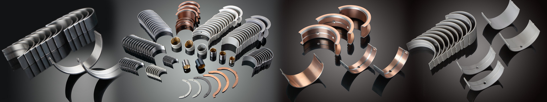
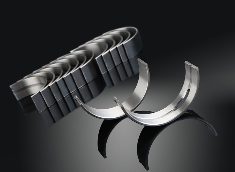
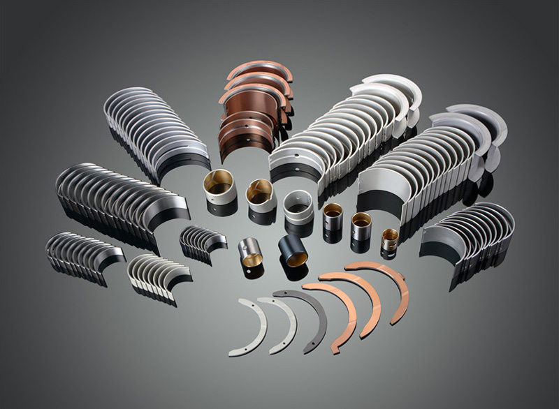

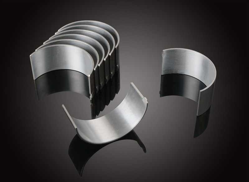
Design feasibility analysis of engine bearing shell
Bush was part of the sliding bearing and shaft contact, very smooth, due to the interruption of supply or supply of lubricating oil, or oil film bearing shell and crank shaft collar no form, in the crankshaft journal and caused half dry friction or dry friction between the bearing shell. Every time occurs, the lack of lubrication and metal bearing temperature rise is not enough to cause bearing bush bearing shell color and overheating, but each part of the direct contact of metals will be bearing alloy be ground down and cause clearance increases, over time, repeatedly both cause bearing excessive wear, make the engine oil pressure drop, resulting in can not run.
Crankshaft bearing working condition is bad, gas explosion pressure and the piston connecting rod set of the effect of inertia force, the force is periodic change with impact load, the maximum pressure of 16 ~ 80 mpa; The relative sliding speed between the journal and bearing shell can reach more than l0m/s, in such a high load operating such a high speed relative motion, will generate a lot of friction heat, make the working temperature of bearing and rising rapidly, at this point if you can't guarantee the fluid lubrication, can make the bearing strong wear. In order to export the heat of friction, reduce the abrasion of the bearing, the design must ensure that sufficient oil is used to pass the bearing.
The crankshaft bearing has a significant impact on the work of the internal combustion engine, which not only affects the reliability and durability of its work, but also affects the potential of further strengthening of the internal combustion engine. Therefore, the design of crankshaft bearing must be given very high attention.
Calculation of the feasibility design of the bearing
1. Axial maximum surface ratio calculation
(1) select the appropriate bearing width of the bearing
According to the main bearing hole powerfully effective width (18 mm) crankshaft main journal and the effective width (18.7 mm), select effective width of the spindle is 16 mm, according to the big hole effective width (18.9 mm) and the crankshaft connecting rod neck width (17.9 mm), select the effective width of connecting rod is 15.2 mm.
(2) the maximum surface of the spindle is more than pressure
The main axial tile under the pressure of burning pressure is much higher than the pressure, and the following formula is adopted for the calculation of the lower surface of the lower tile.
Pj = - mjR two cosine alpha omega lambda mj R 2 cos2 alpha omega
Sigma M = (Pg + Pj)/(SM x delta).
Pg is PI times D over 2 times Pmax
SM = We * dm
In this case, sigma M -- the surface of the main axis is lower than the pressure; Pg - combustion pressure; DM -- spindle tile diameter, dM = 45MM; SM -- the effective bearing area of the spindle tile, = 720mm2; Delta -- empirical value, delta = 1.66; D -- cylinder hole diameter, D = 75mm; Pmax - maximum explosion pressure, Pmax = 10.5 MPa; Pj - reciprocating inertial force; Mj -- reciprocating mass of moving parts, mj = 430.9 g; R -- crank radius, R = 75mm; Omega -- the angular velocity of crankshaft under maximum explosion pressure, omega = 4500 (r/min); Lambda - the linkage ratio is the crank radius/link length, lambda = 0.317; Alpha - crankshaft Angle, alpha = 0 °.
The above data can be obtained on the surface of the main shaft under the maximum pressure under pressure, which is the maximum surface of the main shaft, which is equal to 34.35 MPa.
(3) the maximum surface of the connecting rod is more than pressure
The pressure function of the connecting rod is borne by the burning pressure, which is much greater than the pressure.
Sigma c = (Pg + Pj)/SC
SC = WC by dC
In this case, the sigma c -- the surface of the connecting rod is equal to the pressure; Pg - combustion pressure; Pj - reciprocating inertial force; DC -- connecting rod neck diameter, dC = 44mm; SC - connecting rod tile effective bearing area, SC = 668.8 mm2.
The above data can be obtained on the surface of the connecting rod tile on the maximum explosion pressure. The surface of the connecting rod is equal to the pressure. MPa.
(4) the axial surface is more feasible than the pressure feasibility
Aluminum alloy bearing shell is the biggest pressure under sigma Max can reach 65 ~ 65 mpa, available through the above calculation: spindle tile maximum surface pressure sigma M or less sigma Max, connecting rod maximum surface pressure sigma sigma or less C Max, namely double metal alloy bearing shell can satisfy the use requirement of the engine.
2. One-dimensional simulation analysis of the design stage of the engine bearing shell
CAE analysis USES AVL Excite as the computing platform, and the equivalent calculation model of crankshaft system is built in Exicte to define the design parameters, lubricating oil characteristics and simulation control parameters of each part. Among them, the crankshaft was completed using shaftmodeler and autoshaft, and the connecting rod was completed by conrod modeler.